RZ/G1E SMARC Module
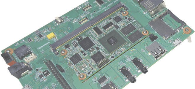
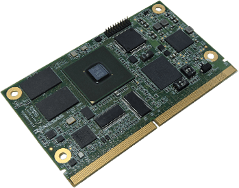
The RZ/G1E SMARC Module developed by Mistral is a small form-factor, high performance module built around 1GHz RZ/G1E Dual ARM® Cortex-A7 microprocessor (MPU) from Renesas. The RZ/G1E SMARC Module and RZ/G1E SMARC Development Kit (SMARC Dev Kit) supports dual camera, dual display ports, dual Ethernet and most of the interfaces of SMARC 1.0 standard. The SMARC Dev Kit has dual board architecture, consisting of RZ/G1E SMARC module and carrier board.
RZ/G1E SMARC Module
RZ/G1E SMARC Module and SMARC Development Kit
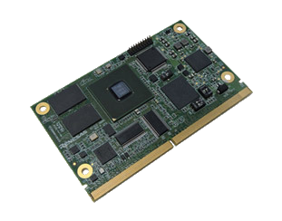
The Renesas RZ/G1E SMARC Module and SMARC Dev Kit from Mistral are small form-factor, high performance module and development platform built around 1GHz Renesas RZ/G1E dual ARM Cortex-A7 processor. Along with 3D Graphics Engine and Video processing units on the MPU, RZ/G1E SMARC Module from Mistral supports dual camera, dual display ports, dual Ethernet and most of the interfaces of SMARC 1.0 standard.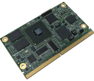
The RZ/G1E SMARC Module and RZ/G1E SMARC Development Kit (SMARC Dev Kit) consist of MPU, PMIC, DDR3, eMMC, Ethernet PHYs, HDMI transmitter, CSI-to-parallel bridge and other interfaces terminated on the 314 edge fingers. The edge fingers can be mated with an MXM3-style socket on the Carrier board. The RZ/G1E SMARC Module is designed in compact size 82mm x 50mm with 1.2mm PCB thickness. This ready to use SMARC module is an ideal building block for any portable or stationary embedded systems.
FEATURES
- Renesas RZ/G1E ARM ® Cortex-A7 Dual Core MPU
- 82mm x 50mm
- 1GByte DDR3
- 4GByte eMMC
- 314 edge fingers as per SMARC 1.0 standard
- Standard Linux kernel 3.10
SPECIFICATIONS
MPU
- ARM Cortex-A7 Dual MPCore 1.0 GHz
- Supports NEON™/VFPv4
- SGX540 3D Graphics Engine
- FHD H.264 video codec
Edge finger interfaces (as per SMARC pinout)
- Display
- HDMI Out
- Parallel LCD display interface
- Camera
- 8-bit Video IN*
- CSI (2-lane) Video IN*
- Connectivity
- Two USB ports
- Two SD interfaces
- Two CAN interfaces
- Two SPI (MSIOF) interfaces
- Four UART (SCIF/HSCIF) interfaces
- One SSI Audio interface
- Four I2C interface
- Four PWM
- Seven GPIOs
- Network interfaces
- 10/100 Ethernet (RMII)*
- Gigabit Ethernet (GMII)*
- Debug
- JTAG
- UART (SCIFA1)
- Power
- IDT PMIC for deriving the power required for processor & to facilitate power sequencing
- 3.3V IO level
- +5V Power Input source from edge fingers
- Mechanicals
- Supports all possible board-to-board stack heights from 1.5mm
- Board-to-board outline and mounting holes are provided as per SMARC standard
- Memory
- 1GByte DDR3
- 4GByte eMMC
- 8MByte SPI Flash (boot source)
*Among these four interfaces only two can be used simultaneously.
For customization or volume pricing, please contact sales@mistralsolutions.com
SMARC Dev Kit
OVERVIEW
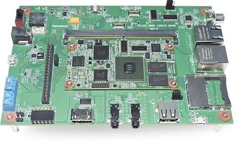
The RZ/G1E SMARC Dev Kit designed by Mistral is a powerful SMARC Development Kit based on 1GHz Renesas RZ/G1E dual ARM ® Cortex-A7 microprocessor (MPU). The SMARC Dev Kit from Mistral has dual board architecture, consisting of RZ/G1E SMARC module and carrier board.
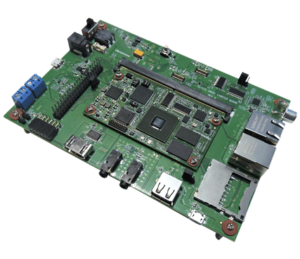 The RZ/G1E SMARC Dev Kit based on the RZ/G1E MPU includes DDR3, eMMC, PMIC, Ethernet PHYs, HDMI transmitter, MIPI CSI-to-Parallel converter and other interfaces terminated on the 314 edge fingers. This module is SMARC 1.0 complaint. The Carrier board on the SMARC Development Kit includes connectors and supporting ICs for validating edge finger interfaces like MIPI CSI and parallel camera, analog video input, HDMI and parallel display, 10/100 and Gigabit Ethernet, USB interface, Audio interface, micro-SD card and SDIO based Wireless module. The SMARC Dev Kit supports additional interfaces like SPI (MSIOF), I2C, CAN, PWM, GPIO, UART (SCIF) on expansion connector/terminal blocks.
A DC jack provided on the SMARC Development Kit serves as primary power source for both RZ/G1E SMARC module as well as carrier board. The RZ/G1E SMARC Dev Kit also provides debug options using JTAG and UART (SCIF) interfaces.
FEATURES
- SMARC based platform for accelerated development
- Dual board architecture:
- SMARC Module : MPU, Memory, PMIC, HDMI transmitter, Ethernet PHY
- Carrier Board: Display, video, audio, wireless, USB, connectivity and other interfaces
- Standard Linux kernel 3.10
- Reusable SMARC module reduces time-to-market and manufacturing complexity
SPECIFICATIONS
SMARC Module:
- MPU
- ARM Cortex-A7 Dual MPCore 1.0 GHz
- Supports NEON™/VFPv4
- SGX540 3D Graphics Engine
- FHD H.264 video codec
- Memory
- 1GByte DDR3
- 4GByte eMMC
- 8MByte SPI Flash (boot source)
- Power
- IDT PMIC support for power sequencing, multi-output power source to processor
- +5V Input supply, 3.3V IO level
- 314 Edge finger interfaces
- Debug
- JTAG
- Dimension
- 82mm x 50mm
Carrier Board:
- Board-to-Board connection
- Low profile 314 contacts, 0.5mm pitch, right angle MxM3 style socket (JAE_MM70-314B2) for edge finger mating.
- 1.5mm stack height
- Video Out
- HDMI connector for interfacing HD (1080p) monitors.
- LCD & Touch connector for graphics LCD module (LXD-M7645A)
- Video In
- MIPI CSI2 Camera module connector for CSI-based camera module (JAL-MIPI-OV5640 V5.0)
- Parallel Camera connector for 8-bit camera module* (JAL-MIPI-OV5640 V5.0)
- RCA jack for analog video input*
- Audio
- Stereo Line-In/MIC on 3.5mm audio jack
- Stereo Line-Out on 3.5mm audio jack
- Memory
- Micro SD card connector for expandable memory
- Wireless
- SDIO card connector for WLAN &BT (SX-SDCAN2-2830) connectivity
- PMOD connector for external BLE module
- Connectivity
- Two USB2.0 connector
- Two RJ-45 connectors
- Two Terminal blocks for CAN interface
- Expansion connector with following interfaces
- One UART(SCIF)
- Two I2C
- Two SPI (MSIOF)
- Three PWM
- Seven GPIOs
- Debug
- Serial Port over USB
- Power
- +5V DC Input
- Dimension
- 160mm x 110mm
*Any one interface can be used at a time
Carrier Board
OVERVIEW
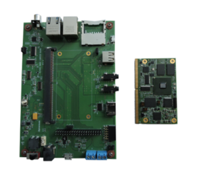
The Carrier board of the SMARC Dev Kit includes connectors and supporting ICs for validating edge finger interfaces like CSI and Parallel camera, Analog video input, HDMI and Parallel display, 10/100 and Gigabit Ethernet, USB interface, Audio interface, micro-SD card, SDIO based Wireless module. The SMARC Dev Kit carrier board supports additional interfaces like SPI (MSIOF), I2C, CAN, PWM, GPIO, UART (SCIF) on expansion Connector/terminal blocks.
 SPECIFICATIONS
- Board-to-Board connection
- Low profile 314 contacts, 0.5mm pitch, right angle MxM3 style socket (JAE_MM70-314B2) for edge finger mating.
- 1.5mm stack height
- Video Out
- HDMI connector for interfacing HD (1080p) monitors.
- LCD & Touch connector for graphics LCD module (LXD-M7645A)
- Video IN
- MIPI CSI2 Camera module connector for CSI-based camera module (JAL-MIPI-OV5640 V5.0)
- Parallel Camera connector for 8-bit camera module* (JAL-MIPI-OV5640 V5.0)
- RCA jack for analog video input*
- Audio
- Stereo Line-In/MIC on 3.5mm audio jack
- Stereo Line-Out on 3.5mm audio jack
- Memory
- Micro SD card connector for expandable memory
- Wireless
- SDIO card connector for WLAN & BT(SX-SDCAN2-2830) connectivity
- PMOD connector for external BLE module
- Connectivity
- Two USB2.0 connector
- Two RJ-45 connectors
- Two Terminal blocks for CAN interface
- Expansion connector with following interfaces
- One UART(SCIF)
- Two I2C
- Two SPI (MSIOF)
- Three PWM
- Seven GPIOs
- Debug
- Serial Port over USB
- Power
- +5V DC Input
- Dimension
- 160mm x 110mm
*Any one interface can be used at a time
Software
The RZ/G1E SMARC Module and SMARC Dev Kit comes with BSP Binaries Standard Linux kernel 3.10 that will be available online. The software package consists of:
- SPI-loader and uBoot
- Yocto Linux Drivers and BSP (Linux Version 3.10)
- Drivers
- Camera
- Audio
- WiFi & BT
- LCD + Touch screen
- HDMI
- USB
- RMII, GMII Ethernet
- Serial port
- SD/eMMC
Infographics

About SMARC
SMARC (‘Smart Mobility ARChitecture’) is a specification published by the Standardization Group for Embedded Technologies e.V. (SGET) for computer-on-modules (COMs). The SMARC (“Smart Mobility ARChitecture”) is a versatile small form factor computer Module definition targeting applications that require low power, low costs, and high performance. The SMARC Modules will typically use ARM SOCs similar or the same as those used in many familiar devices such as tablet computers and smart phones. Alternative low power SOCs and CPUs, such as tablet oriented X86 devices and other RISC CPUs may be used as well. As per the standard, two Module sizes are defined:
- 82mm x 50mm
- 82mm x 80mm
The Module PCBs have 314 edge fingers that mate with a low profile 314 pin 0.5mm pitch right angle connector (the connector is sometimes identified as a 321 pin connector, but 7 pins are lost to the key).
The Modules are used as building blocks for portable and stationary embedded systems. The core CPU and support circuits, including DRAM, boot flash, power sequencing, CPU power supplies, GBE and a display transmitter are concentrated on the Module. The Modules are used with application specific Carrier Boards that implement other features such as audio CODECs, touch controllers, wireless devices, etc. The modular approach allows scalability, fast time to market and upgradability while still maintaining low costs, low power and small physical size.
Click on the links below to access the design guides and specifications documents:
SMARC Design Guide V1.02.0 M (SMARC DG V1p0.pdf)
SMARC Hardware Specification V1.11.9 M (SMARC Hardware Specification V1p1.pdf)


