Airborne Electronics – Airworthiness Regulations and Safety Requirements
The growing demand for high-efficiency fighter aircraft, commercial airbuses and the ever-evolving Aerospace and Defense technology landscape is driving the demand for next-gen Airborne Electronics. Air transportation agencies and aviation OEMs across the globe have been striving to build futuristic Airborne Electronics systems to make flying more reliable, predictable, and safer.
Airborne electronics sub-systems such as communication modules, transmit-receivers, flight control computers, guidance & navigation systems, and fire-control systems among others are some of the critical components of an aircraft. The design of Airborne electronics systems and sub-systems demands higher safety and reliability to make sure airworthiness of these sub-systems. All major avionics OEMs, R&D and System Engineering companies designing airborne electronics hardware and software have to make sure compliance with several regulatory standards like DO-254, DO-178B/C, ARINC, MIL-STDs, and DO-160 to develop high performance, reliable products.
This blog outlines some of the major airworthiness regulations and safety requirements for airborne electronics followed by global OEMs.
Airborne Electronics – Standards
DO-178B/C – Software Considerations in Airborne Electronics and Equipment Certification
The DO-178 Standard for Software Consideration in Airborne Systems & Equipment Certification is laid out by RTCA in 1992. Over the past two decades, the aviation industry has evolved tremendously – both in airborne electronics hardware and software. Aviation OEMs have introduced advanced and more effective methodologies such as Model-based Software Development & Verification and Object-oriented Program in airborne software development. Considering such developments and industry demands, in 2011, RTCA published DO-178C, a revised version of DO-178B. DO-178C addresses several issues in the older version and is comparatively more structured and precise to ensure consistency in the design process.
The DO-178C standard defines Design Assurance Levels (DALs) for airborne software, categorizing the severity of potential software failures and their impact on the overall system. Similar to the DO-254 standard, DO-178C identifies five assurance levels. The table below provides a summary of these DALs.
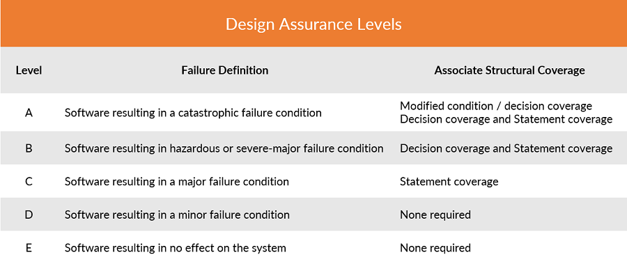
Airborne Electronics – Design Assurance Levels
The development of DO-178B/C compliant software needs a good amount of experience and expertise in several design, testing and verification tools and methods. The DO-178C based software testing involves three levels as described in Section 6.4 of the standard viz., Low-level testing, software integration testing, and hardware/software integration testing. DO-178B/C assures the agility and reliability sought during the development and testing of airborne software.
DO-254 – Design Assurance Guidance for Airborne Electronics Hardware
DO-254 is a stringent functional safety standard that defines and regulate the process of auditing and certification of Airborne electronics systems. DO-254 is published by Radio Technical Commission for Aeronautics (RTCA) in 2005 and administered by the FAA to ensure safety in electronic-airborne systems. The standard insists on tracking the developmental activities and documenting every step and each stage involved. The standard helps minimizes errors in the process of a design and brings traceability to a great extent.
DO-254 covers the guidance for airborne electronics hardware such as,
- Line Replaceable Units
- Circuit board assemblies
- Programmable components such as field-programmable gate arrays (FPGA), programmable logic devices (PLD), and application-specific integrated circuits (ASIC)
- Commercial off-the-shelf (COTS) modules.
DO-254 defines five levels of compliance, based on the impact of hardware failure on the aircraft or its functions. Level A, being the most stringent (termed as catastrophic), and Level E with least impact (termed as No safety) on passengers/crew. This means that achieving Level A compliance for airborne electronic systems involves a significantly more complex verification and validation process compared to Level E compliance.
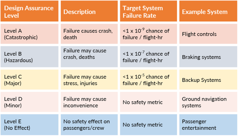
DO-254 covers the following aspects of Airborne electronics Hardware design processes
• Requirements Capture
• Conceptual Design
• Detailed Design
• Implementation
• Verification
• Transfer to production
DO-160G Environmental Conditions and Test Procedures for Airborne Electronics
DO-160G outlines procedures and environmental test criteria for airborne electronics. Vital airborne electronics systems must be designed to withstand diverse environmental conditions it may subject to during the flight. To standardize the design, production and testing of these complex, classified aircraft electronics, in 1980, RTCA published DO-160 – Environmental Conditions and Test Procedures for Airborne Equipment.
Airborne electronics systems, small or big, have to undergo DO-160 testing. The standard covers testing of a vast range of critical factors such as temperature, humidity, electrical interference, shock resistance, flammability, magnetic effect, waterproofness, radio frequency susceptibility, lightning direct effects and operational shocks among others, that can impact the performance of an airborne electrical or electronic device. By subjecting airborne electronics to DO-160G certification and testing process, the equipment confirms to deliver reliability, accuracy and robustness in any flight condition.
ARINC 661 – Development of Cockpit Display Systems
Aircraft cockpit displays have been becoming increasingly complex over the past two decades due to the stringent certification requirements defined by DO-178B/C. The ARINC 661 is a set of specifications that encourage a standard, flexible architecture for the avionics cockpit systems. ARINC 661 outlines the specifics for Cockpit Display Systems (CDS) and the communication between CDS and User Applications (UA), which control and monitor airborne electronics and subsystems. The standard was first published in 2001 and over years it has evolved adding several supplements such as widgets for vertical maps, Multitouch management, Animated graphics, 3D maps, improvements in user interface, etc.
The ARINC 661 Standard also outlines GUI definition for CDS. The standard brings out a clear separation between graphics codes, logic codes and the layout of all visual elements. ARINC 661 brings out a standard communication protocol for the CDS and UA to exchange messages.
Modern cockpit designs are increasingly adopting the ARINC 661 Standard. The standard is used right from requirements specification, design, and development through deployment and maintenance of airborne display systems. The objective of the standard is to efficiently manage the increasing complexity of Cockpit Display Systems. The standard aids easy integration of new avionic systems, display functionalities and Cockpit HMI upgrades into aircraft in business – all while minimizing the cost implications.
ARINC 661 Structure,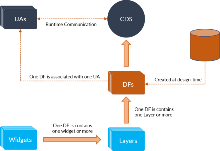
- User Application – System application interacting with the CDS
- Cockpit Display System – Graphics Server that displays and manage the Graphical User Interface (GUI)
- Definition File – GUI definition associated with User Application
- User Application Layer – GUI container for widgets, the basic building block of the GUI
MIL-STD-704
MIL-STD-704 deals with the electric power characteristics of an aircraft and defines a standardized power interface to ensure compatibility between the aircraft power system and airborne electronics. The standard addresses various power characteristics such as voltage, frequency, phase, power factor, ripple, maximum current, electrical noise and abnormal conditions for both AC and DC systems in an aircraft. Published in 1959, MIL-STD-704 supersedes the engineering document MIL-E-7894 describing aircraft electrical power.
MIL-STD-704 outlines several distinct operating conditions for an aircraft electrical system such as normal operation, power failure, engine starting, abnormal electrical power, power transfers, etc. Any airborne electronics equipment designed should address these operating conditions and meet the performance criteria defined depending on its criticality.
Developing airborne electronics systems and sub-systems from scratch involves a tremendous amount of effort, time and cost. Employing safety-certifiable COTS airborne electronics hardware modules in avionics designs enables the developers to kick-start the project faster. In addition, the use of safety-certifiable COTS modules helps the developers effectively manage the challenges of several regulatory requirements such as documentation, component certification and risk mitigation. Thus, safety-certifiable COTS modules and systems significantly reduce development time, cost, and overall certification efforts.
Conclusion
Extensive experience and expertise in airborne electronic hardware, airborne embedded software, and Hardware-software integration, and system simulation is necessary to develop airborne systems that meet stringent regulatory needs. High competence in the verification and validation of safety-critical hardware and software is also a necessity.
Mistral is an Aerospace and Defense technology design company providing robust, high-performance Airborne electronics to leading Defense organizations in India. Mistral brings several advantages to the table. Our two decades of experience and expertise developing cutting-edge airborne electronic systems that conform to various avionics safety standards assure faster time to market. Mistral’s design expertise and established development methodologies, proven over numerous safety-critical system deployments and partnership with global safety-certifiable COTS solutions providers, offer the latest and robust avionics hardware and software solutions.
To know more about Mistral’s avionics hardware and software development services and expertise, write to us.

