Introduction
A Tech. Brief post in August 2010 – Border & Coastal Surveillance – provided an overview of a Border/Coastal Surveillance System (B/CSS) using the C4ISR concept. The post covered the operational components of such a solution: the sensor network, the Command & Control (C&C) application, and the operator.
This post describes a sensor architecture that can be implemented for coastal surveillance in India. This is a pertinent topic, given that a day last week marked the second anniversary of the start of the Mumbai terror attack.
Identifying Friend or Foe
Following on the 26 November, 2008, Mumbai terror attack, the Government of India has initiated several steps towards ensuring that such an attack will never again hold the nation to ransom, or cause such loss of life and damage to property. Given the ease with which the attackers landed in Mumbai, one of the key initiatives is targeted at plugging the holes in the Indian coastal security network.
Apart from improving the coastal police network in terms of presence and equipment, the initiative entails the registration of all seaborne vessels (fishing and non-fishing) plying in India, as well as the installation of transponders on all types of boats. All vessels over 20 metres length will have to install AIS (Automatic Identification System) class B transponders. For vessels under 20 metres length, a committee, under the Director General, Indian Coast Guard, has been constituted to decide on the type and technology of transponder to be used.
 |
| Figure 1: AIS for Ships (Source: Wikipedia.org) |
With the establishment of a coastal AIS chain, to be initiated by the Ministry of Shipping, near real-time data on the movement of all registered shipping vessels will finally be available.
Sensor Architecture
The proposed sensor architecture does not require the above infrastructure (transponders on all seaborne vessels and a chain of interconnected AIS databases): however, its presence will reduce False/Nuisance Alarm Rate (FAR/NAR).
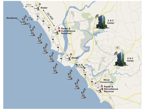
The proposed architecture consists of two layers of sensors, connecting to a nodal C&C Centre, which in turns connects to an Emergency Operations Centre.
 |
| Figure 2: Two-layer Sensor Architecture |
Layer 1:
The first layer of sensors will be relatively long-range sensors with not a very high level of resolution. The sensor network will consist of Radar, Sonar (optional), and Surveillance Receiver.
- Radar: L/S-band Radars will be used. These will have a detection range of approximately 30 kms. The radars will be housed in shelters about 500 metres from the High-Tide Line (HTL) – CRZIII – and there will be a radar every 50 kms. along the coastline.
- Sonar: A passive sonar network can be optionally deployed. The sonars will be deployed using fixed sonobuoys, approximately 1 km. into the sea. The sonobuoys will be spaced 10 kms. apart in the sea, and will follow the contour of the coastline.
- Surveillance Receiver: The surveillance receiver network will be used to monitor radio and data transmissions. The surveillance receiver can be housed in the same shelter as the radar, except that there will be one surveillance receiver every 100 kms.
Layer 2:
The second layer of sensors have a shorter detection range, but offer a significant increase in the resolution of the captured surveillance data. This layer will operate in tandem with Layer 1, in that entities identified in Layer 1 will have their coordinates passed on to the sensors in Layer 2, for further detailing. Layer 2 sensors will consist of 1, 2, or 3 different types of PTZ video surveillance cameras, housed together.
- Thermal Imaging Camera: A network of thermal imaging cameras, with an object detection range of over 5 kms. will be used for night surveillance. These cameras will be located along the coastline, at 10-kilometre intervals. At locations where radars are also positioned, the cameras will be housed in the same shelters as the radars.
- Active Illumination Camera: In case covert surveillance is not a pre-requisite, active illumination cameras may be used instead of thermal imaging cameras at night, and function during the day as well. Alternatively, if higher resolution is required at night, as the entity-under-surveillance gets closer, an active illumination camera can supplement the capabilities of the thermal imaging camera. These cameras will be co-located with the thermal imaging cameras, if used together; otherwise, they will be located in the same manner as thermal imaging cameras.
- Optical Camera: In the event that it is decided that thermal imaging cameras will be used for surveillance at night, mid-to-high resolution optical cameras can be used for surveillance during the day. Based on the requirements of the user, a variety of PTZ cameras, differentiated on resolution, are available. The arrangement for locating these cameras will be the same as for the other types of cameras.
Layer 3:
The Nodal Command & Control centre run a C4ISR application that allows users to integrate the sensor feed from the sensors in layers 1 and 2, and then plan a response. There will be a 2 Mbps wired link, with a wireless back-up, between sensors in a 150 kms. contiguous line and the Nodal C&C. The Nodal C&C will serve as the data repository for the sensors in its geography, as well as the first line of decision-making, in the event of a crisis. Nodal C&Cs will be in a position to share data amongst themselves.
Layer 4:
The Emergency Operations Centre (EOC) links various Nodal C&Cs together, and forms the next level of decision-making in the coastal surveillance system. Depending on the size of the of the area-under-surveillance, one or more EOCs may be set-up. The EOC will have a dedicated 10 Mbps data link, wired and wireless, to allow multiple nodal C&Cs to transmit data to it. The EOC too runs a C4ISR application, and integrates data from the nodal C&Cs to present a Common Operational Picture (COP) to top-level decision-makers.
Conclusion
The above architecture is a practical and robust design for Indian requirements. The technologies used are proven and cost-effective. India has a coastline of over 7,500 kms., of which more than 5,400 kms. is the mainland coastline. Any coastal surveillance system entails a significant investment on the part of the government, and it needs to be seen if this investment is commensurate with the potential risk of that part of the coastline being used for activities detrimental to functioning of the state and to the well-being of its citizens.
Mistral offers the Amper C4ISR nemesis product line for Homeland Security needs in India. Amper’s nemesis BSS solution is targeted at governments requiring real-time monitoring and control of their borders and coastlines. Given below is a case study a C4ISR B/CSS implementation in Spain, covering Spain’s maritime border with North Africa (specifically Morocco). The problem Spanish authorities had was that this stretch of the maritime border was being used for illegal immigration and drug smuggling, and that the number of incidents were increasing at an alarming rate.
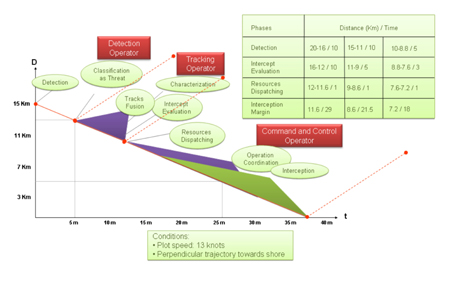
The graph on the right plots the progress of the entity-under-surveillance towards the Spanish shore, with distance from the shore being plotted on the Y-axis, and elapsed time since detection being plotted on the X-axis. The table on the right provides the phase-wise figures for three scenarios – detection at 20 to 16 kilometres, 15 to 11 kilometres, and 10 to 8 kilometres.
 |
| Figure 3: Coastal Surveillance System: Spanish Case Study – Typical Operational Performance |


