Automated Test Equipment (ATE) for Testing RADAR Transmit Receive Modules
Introduction – Automated Test Equipment
Automated Test Equipment (ATE) is a computer-based system that uses test and measurement instruments to perform and evaluate the results related to functionality, performance, quality, and stress testing of a product. As its name implies, ATE automates testing processes with nil or minimal human intervention.
 This case study outlines Mistral’s expertise in developing an Automated Test Equipment which can be used to test various parameters of a Transmitter Receiver (TR) Module that is part of a RADAR. The ATE automates testing of transmitter parameter measurements such as Transmitter Harmonic Rejection measurements, Tx Gain Matching, Transmit Power; receiver parameter measurements like, S-parameter measurements [Receiver Gain, return loss (input and output), Phase shifter measurements] and BITE Measurement among others.
The Customer
The customer is a defense R&D organization focused on the design and development of advanced embedded systems for a variety of cutting-edge applications, including RADAR, Direction Finding (DF), Electronic Warfare, and Airborne Systems, among others.
The Requirement
The customer approached Mistral to design and develop their new S-band RF Transmit Receive Multi-modules (STRMM). The Transmit Receive Multi-module (which consists of multiple TR Modules) is a key component of Phased Array RADARS operating in S-Band and is manufactured in large volume. Each TR module had to be tested during the development and production phases for a range of functional, performance and environmental parameters. The customer was keen on completing the testing within a defined time frame; however, the manual testing of individual module was consuming around three days, which would have taken over two years to complete the testing process of all units! To address this, Mistral came up with a strategy to automate the testing process. The aim was to build an Automated Test Platform which effectively manages a large number of diverse measurements and bring down testing time by ~75% to ensure timely delivery and deployment of STRMM units.
The Solution – Automated Test Equipment
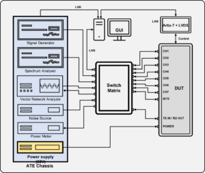
Mistral designed and integrated an Automated Test Equipment (ATE) framework capable of supporting a frequency range from 1GHz to 24GHz. The ATE framework consists of a Rohde & Schwarz RADAR Test System, Xilinx Artix-7 FPGA Board, and a custom-built Test Suite to automate various tests. The ATE is designed to perform fast, automated RF measurements of the TR Modules during development and production phases. The system self-calibrates after every measurement cycle and performs a complete hardware calibration in case of any changes in the test setup.
Hardware
The Automated Test Equipment consists of various test and measurement instruments and accessories that aid testing of the TR Multi-module. The Automated Test Equipment integrates a 24GHz Signal Generator, Spectrum Analyzer, Vector Network Analyzer (With continuous sweep up to 24 Ghz), Switch Matrix, Power Supply Unit, Controller Module, Noise Source, Power sensor, RF Signal Conditioning and DUT Multiplexing Unit, and Test Manager PC (Test Suite Host PC). The system provides multiple USB Hubs and Ethernet ports to interface with Device Under Test (DUT) and Host PC. 
Mistral used an off-the-shelf FPGA based card with customized RTL code and embedded software to interface between DUT and the test framework. The board is used to generate Pulsed signals to analyze Transmit Measurements like Harmonics, Tx power, etc. and communicate with the Host PC.
The Automated Test Equipment is designed to perform Functional Testing, Stress and Performance Testing, Environmental Stress Screening (ESS), among others. It supports over 26 different test cases and 70,000 plus measurements. The ATE enables 90% of automation coverage, and manual intervention is required only to connect the DUT and test probes.
Highlights:
- Supports 7+-channels and 40+ frequency spots which can be customized to any number of channels and frequency spots.
- Measures Transmit power, Rise Time, Fall Time, Pulse Width, Droop for Transmit signals
- Measures Transmitter Gain, Phase Shift, Input Return Loss, Output Return Loss (Tx S parameters)
- Measures Tx Harmonics Rejection, Tx Spurious Rejection, P1dB (Compression Point)
- Receiver Gain, phase shift, Input Return Loss, Output Return Loss (Rx S-parameters)
- Receiver Noise Figure measurement
- Power Efficiency Measurement
- Band Pass Filter Characteristics
- Test Automation for Raw Data collection and Calibration of DUT as well as instruments.
- Instrument Calibration data is also automatically attached to test reports.
ATE – Test Suite and Test Framework
The Test suite is developed using Python and C#, uses various libraries like PyVisa and Python excel and runs on both Windows as well as Linux PCs (Host). It is flexible to be used with various instrument makes like Keysight as well as Rhode and Schwartz (R&S).
The suite is provided with Command Line Interface as well as GUI for test management. The test suite supports testing of 56 channels in one cycle without changing test setup. The ESS tests were carried out using Keysight Instruments with Python Code.
The ATE Test Suite takes care of configuration of measuring instruments and the DUT, in addition to the execution of various test cases including Functional Testing and Environmental Testing. This system does post processing of collected data and automatically generates final test reports in Excel and PDF. The ready to print reports can be submitted to certifying agencies for Product certification. Test framework can also print the reports on a configured printer. Mistral developed a reusable test framework for the ATE.
The framework is easily adaptable for testing products such as Channel Receivers and Single-Chip Tx/Rx Modules, with minimal customization required. It is compatible with a wide range of Test & Measurement instruments from leading manufacturers like Rohde & Schwarz, Keysight, Tektronix, and others.
The test framework uses SCPI protocol on TCP/IP to communicate with various instruments and DUT for the test automation. SCPI protocol is a standard for syntax and commands to use in controlling programmable test and measurement devices.
Datasets

STRMM Attenuator Measurement in Receive Mode
The Automated Test Equipment measures more than 70,000 data points for each Device Under Test and reduces the testing time by 75% compared to manual testing. It offers accurate and error free data with logs recorded for future reference. The ATE can test scale up to test 56 channels in a go without changing the test setup, which helps to save time and effort. The ATE enables remote monitoring of the test setup using a camera and power cycling any of instruments and the DUT. It also features a mechanism to automatically monitor and control of chamber temperature.
User Interface
The Automated Test Equipment is integrated with an easy-to-use Python-based UI/UX to enable unit testing, device bring-up testing, ESS testing and configuration of the device under test (DUT).
How the system works?
The user can select various parameters such as Start Frequency, Stop Frequency, Frequency Step Size, Input Signal Amplitude, Input Power Level, Channel Number, Attenuator Value, Pulse Width and Duty Cycle among others for the test cases from the user interface. The Automated Test Equipment executes the tests and generates results. The Signal generator generates a signal of a given frequency and transmits it to the STRMM Module through the Switch Matrix.
The Multi-channel switch matrix, connected to various TR Modules of STRMM, switches the signal over channel-1 to TR-1. The output from TR-1 is switched to the Spectrum Analyzer for measurements. The Switch Matrix switches the Signal over Channel-2 to get the results of TR-2 and so on. The test cycle will be repeated for varying frequency and signal types until all the parameters defined are completed. The whole process is automated using different test scripts. The user can execute various test cases from the user interface provided.
To read the full case study, please download the PDF!


